 |
| Demonstration the problem with Section View |
The following blog is describing how the one can create break-out section views for engineering drawings, using Siemens UNIGRAHIX NX software.
I personally find NX Drafting a long, time taking process therefore it's always good to have some tricks handy. (Click on images to obtain full size.)
I personally find NX Drafting a long, time taking process therefore it's always good to have some tricks handy. (Click on images to obtain full size.)
The problem:
If the one would like to create a half section of an object on different projections, there is a tool called "Section View" which can create a view from any parent drawing view but it will require always to have both views shown.

This can be done by simply clicking at the desired point (with Dynamic Section Line definition) or by creating a sketch for the section line (with Select Existing). This second option requires a sketch that can be created with the "Section Line" option.
However, any of these options will make the section and add the cutting lines, arrows and lettering, which is unwanted. Any half-projection is requiring a different and complex method.→ The question arises, how to make a proper half-section then?
Step-by-step solution:
 |
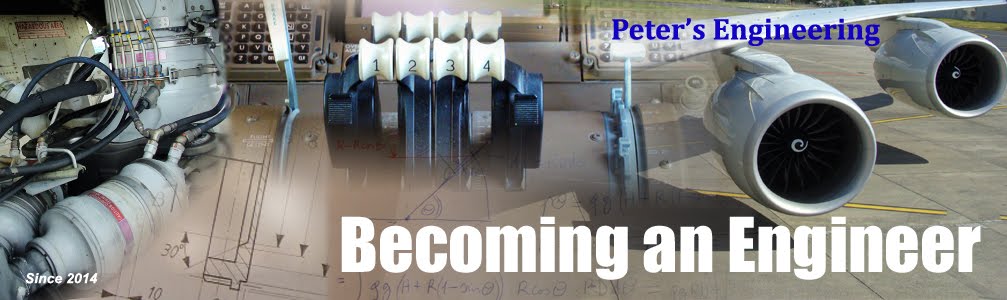
| Simple Assembly |
(For the demonstration, a simple composite wall, with integrated sleeve and bolt is assembled. This is just a simple, quick model, no guarantee of correct alignment of elements and dimensions.)
1. Place a top view and a side view.
2. Activate the view that you would like to have half sectioned.
3. Draw a circle/Studio Spline around the area that encloses all the components that you would like to cut in half. Then Finish Sketch.

4. Select Break-Out Section option:

- "Select view for break-out creation": Select the drawing frame of the view where you want the section to be.
- "Define base point - Select object to infer point": In this step, you need to use the other view, and select a point through which the cut will be done on the other view. (in most cases it lies on a symmetry plane or a center of a circle)
- "Define the extrusion vector or continue to accept the default - Select objects to infer vector": You may accept or reverse the vector in which direction the cut will be made. An orange arrow shows this on the view where the base point was selected. If you accept direction, continue with next step without clicking anything here. If not, reverse vector.
- Click on "Select Curve" and "Select break line near start": then you need to select the previously drawn circle or spline curve.

- Click Apply and wait for the half section to be loaded.
 |
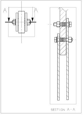
| Half-section after Break-Out View |
5. Now you can delete the other view that was only needed for selecting the "Base point". This way you can only have one view and not like in the case of Sections with arrows.
Note that after completing a break-out section, no modification is possible. The same is true after deleting the second view, it has to be added again and start the whole process from the beginning.
Next part deals with correcting the view for engineering drawing compatibility. (Here is where your theoretical knowledge comes in, since any CAD software you're using, won't tell you how to do so. You as an engineer/designer need to know the correctness of your drawings!)
Adding and removing hatching on object:


It may seem in some cases that there is no hatching on a surface. If you look carefully, you will find a tiny line that is part of hatching but the distance is too large between the hatching lines. In such case, changing the distance of the hatching lines will solve the issue.

To get rid of hatching where it is not needed:
(e.g. Bolts, pins, washers, shafts should never be hatched.)
Use: Section in View:

- Select View: Drawing frame- Select Object: I recommend right-mouse-clk on the object and "Select from list..." that is hatched and select proper one corresponding to the object. In this case, you will always select the right object, not the one that NX offers first.- Action field: Select "Make Sectioned"- Ok/Apply- Right clk on drawing and update view. Only then you will see the change.
-------------------------------------------------------------------------------------------------------------------------
Possible problems that might occur:
According to NX detailed description, the one can check the following things to solve the problem:
Recommended Actions
-------------------
o Choose Ignore to restore the view to the state it was in
prior to the update. This is the DEFAULT action.
o Choose Suppress to convert the view to manual update.
o Choose Delete to delete the view and all associated objects.
Possible Corrective Actions
---------------------------
o Validate and fix the model
o Set view to manual update
o Set view to reference
o Recreate view
o Remove view
o Suppress view update
o Fix invalid section lines
o Validate layer settings
o Unsuppress suppressed solid bodies
o Re-establish section segment associativity in
Edit Section Line