This blog is meant to give a basic definition about the wingtip vortices and to give a sense of the lifting-line model of a finite-span wing.
Tip vortices and down-wash generated behind an
airplane are shown.
You may see on the pictures the tip vortices that are visualized by the clouds. On the second picture, there's a plane shortly after take-off,
very high angle of attach, so there is a very huge lifting force of course, and
you can see the vortices generated and their mixing in the air with the upstream and downstream flows.
Another picture of an
agriculture airplane of which's tip vortex is visualized. Significant is the size of the vortex and its huge intensity, compared to the size of the aircraft.
The following figure is
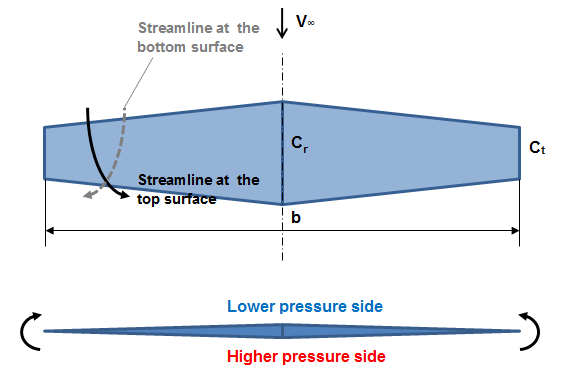
showing the visualization of flow past a rectangular wing. Due to the pressure difference between the upper part and the lower
part and the fact that the wing has a finite span, there will be a certain
tendency of the air to flow from the higher pressure to the lower pressure
part. We have counter rotation vortices at the ends of the wing. If I have a streamline at the bottom
surface then near the wing tip it’ll be deflected as it’s indicted with the
dashed line. On the other side, on the suction side, the streamlines will be
deflected towards the fuselage.
Initially it was very
difficult to create a realistic geometric model of this type of the vertical
wake so they came up with an idea; instead of taking this spiral folding, make our “vortical” wake behind the airfoil
completely flat. It doesn’t mean
that there will be no vorticity. It means that the self-induction is completely
neglected and the vertical flow is assumed to be completely flat. It’s of
course not true but we can build the model of the wing.
Flow past a wing is modeled
by the superposition of the uniform free stream and the velocity induced by a
plane vortex sheet “pretending” to be the cortex wave behind the wing.
The idea of Prandtl was
that; imagine if we have infinitely many vortex lines, of which each of them
has such shape as shown on the figure:
(It extends from infinity
along what is called a lifting line, which completely replaces the wing and
goes back to infinity.) These infinitely many vortex lines are overlapping along
the lifting line. Beyond the lifting line they form a vortex sheet which is a flow-stream with distributed vorticity. Where they
overlap, they create an infinitesimal contribution to "gamma" – dГ, to the total
vorticity – Г(y). Since they overlap, Г will have a symmetrical distribution.
Each of these lines is called a horseshoe vortex.
 |
| Rohács József, Gausz - BME - Aerodinamika page 78.Figure 4.4. |
In other words, the vortex
sheet behind the wing is “woven” from continuum of infinitesimally weak
horseshoe vortices. These vortices are “attached” to the lifting line leading
to a continuous distribution of circulation along the wing span.
We’d like to calculate the
velocity, induced by this vortex sheet along these lines. Each of these
horseshoe vortices induces a certain velocity distribution along y line, which
is completely vertical, which means that higher velocity is in z direction. Next
it is assumed that each infinitely thin slice of the wing generates the
(differential) contribution to the total aerodynamic force as it were a 2D
airfoil. Each slice “senses” its individual direction of “free stream”, which
results from the real free stream vector V∞ and the vertical (normal to the vortex sheet)
velocity induces at the lifting line in the point corresponding to the position
of the wing slice.
References:
Photos: Airliners.net, NASA.gov
- Timo Harsch - Airbus A340-642 ZS-SNG
- Colin Hollywood Photography - Boeing 777-F6N B-2083
- Helmut Schnichels - Airbus A380-842 VH-OQA
- Aerodynamics lecture, by Jacek Szumbarski, Warsaw University of Technology
- Rohács József, Gausz - BME - Aerodinamika jegyzet, page 78. figure 4.4.


No comments:
Post a Comment